
Wiring diagram:
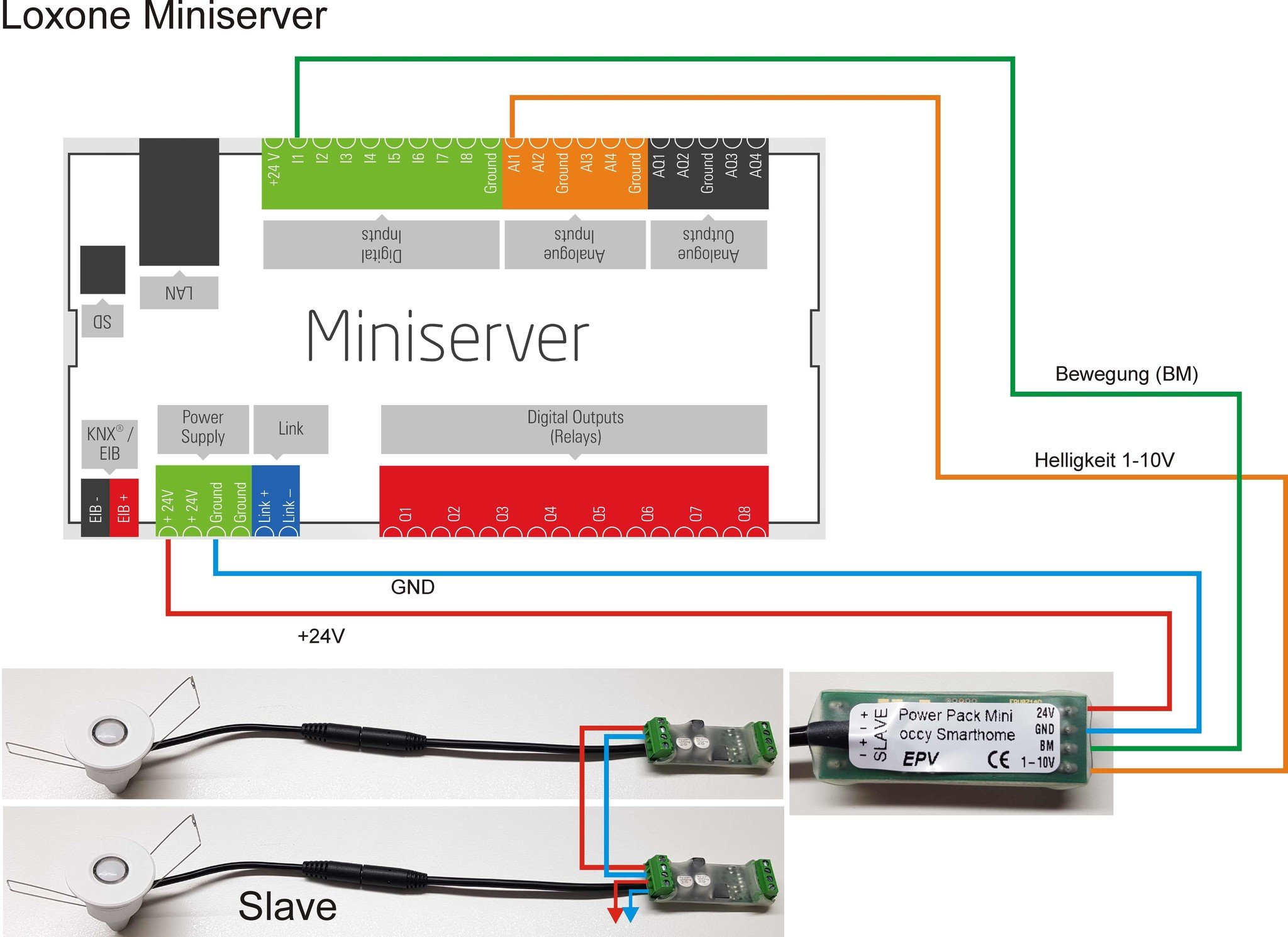
Connect the motion signal to the digital input:
Connect the motion signal of the sensor (BM) with one of the digital inputs I1 to I8.
The output of the occupancy sensor is designed as a push-pull.
Connect brightness value to the analog input:
Connect the light value signal of the sensor (1-10V) to one of the analog inputs AI1 to AI4.
The occupancy sensor displays the light value as a 1-10V analog value. With more light in the room, the voltage increase. (0V = 0 lux, 10V = approx. 1000 lux).
Terminal pin assignment of the occupancy sensor:
| terminal pin assignment of the presence detector | description | value |
| 24V | supply voltage | 15 – 28 V DC |
| GND | ground / GND | 0V |
| BM | motion | detected movement = approx. supply voltage no movement = 0V max. 10 mA active/passive |
| 1-10V | brightness | 1-10V (0V = ca. 0 Lux, 10V = ca. 1000 Lux), (max. 10 mA) |
| SLAVE + | SLAVE-extension | Two-wire line |
| SLAVE - | SLAVE-extension |
Pin connection Loxone Miniserver:
| I1 – I8 | Digital inputs | Internal input resistance: 10kOhm Max. 100 mA • 0-7.2 V corresponds logically „0“ • 7.0-8.2 V = switching threshold bzw. |
| AI1 – AI4 | Analog inputs | 0-10V DC, resolution10 Bit, internal input resistance 10kOhm Also usable as digital input (24VDC) • < 1V corresponds logically „0“ • 1 - 24V corresponds logically „1“ |
| Q1 – Q8 | Analog inputs (Relais) |
250 V AC 5A at cos phi =1, 30 V DC 5A (With higher loads an auxiliary relay must be used) |
| AQ1 – AQ4 | Analog outputs | 0-10V DC, resolution 12 Bit, max. 20mA output load |